A PHY Configuration consists of:
- One Clock Lane Module, and
- One or more Data Lane Modules
Each Lane Module communicates with its counterpart across the interconnect using two signal lines.
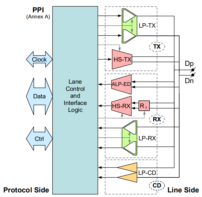
Functional Components of a Lane Module
Each Lane Module contains:
- High-Speed (HS) functions (using both wires together; differential)
- Low-Power (LP) functions (operating on each wire individually; single-ended)
- Control and interface logic
- (Optional) Alternate Low-Power Exit Detector (ALP-ED)
Signal characteristics:
- HS signals: low voltage swing (≈ 200 mV)
- LP signals: high voltage swing (≈ 1.2 V)
Usage:
- HS functions → high-speed data and ALP communication
- LP functions → control signaling and optional auxiliary uses
The Lane Control and Interface Logic coordinates all functions and interfaces with higher-level protocol layers.
What Happens Inside a Lane Module?
| Mode | Purpose | Speed | Signal Strength | How it Works |
|---|---|---|---|---|
| High-Speed (HS) | Sending big data fast (like video frames) | Very fast | Small voltage (tiny electrical changes) | Uses both wires together as a pair (differential) |
| Low-Power (LP) | Sending small control commands (like start/stop) | Slow | Larger voltage | Uses each wire individually (single-ended) |
| There is also an optional Alternate Low-Power (ALP) mode for special low-power communication. |
High-Speed Functions
- HS-TX: Differential high-speed transmitter
- HS-RX: Differential high-speed receiver
A Lane may contain:
- Only HS-TX
- Only HS-RX
- Both, but they are never enabled at the same time
When enabled, HS blocks provide termination for the lane.
When disabled, they enter high-impedance state.
Low-Power Functions
LP functions consist of:
- LP-TX (single-ended transmitter), possibly supporting Low Voltage Low Power (LVLP) mode
- LP-RX (single-ended receiver), always active when powered unless in ALP mode
- LP-CD (Contention Detector), required only for bi-directional LP operation
LP-CD checks for line contention (avoid both sides driving at once) before driving new states (except in ULPS).
Alternate Low-Power (ALP) Functions (Optional)
Available when ALP mode is supported:
- ALP transmitter (capable of driving both lines to ground)
- ALP Exit Detector (ALP-ED) (required in all Lanes if ALP is supported) → used to detect when to leave ALP mode and return to normal operation
- ALP receiver
ALP mode shares HS-TX / HS-RX hardware, with ALP-ED added for detecting exit conditions.
Functional Correlation Rules
| If the Lane has… | It must also include… |
|---|---|
| HS-TX | LP-TX |
| HS-RX | LP-RX and (if ALP supported) ALP-ED |
| Additionally: |
- If LP-RX is powered → it stays active unless in ALP mode.
- In ALP mode, LP-RX is disabled and ALP-ED monitors the line.
The HS-TX, LP-TX, and HS-RX functions never operate simultaneously except during short transition periods.
Lane Matching Requirement
For correct operation:
- Each transmit function on one side must have a corresponding receive function on the other.
- LP contention detection is needed when TX/RX coexist and LP bi-directional signaling is supported.
- ALP receive support must be provided in Lane Modules when ALP mode is enabled.